5.1 The Guide McStas Component
Neutron guide.
Identification
-
Author: Kristian Nielsen
-
Origin: Risoe
-
Date: September 2 1998
Description
Models a rectangular guide tube centered on the Z axis. The entrance lies in the X-Y plane. For details on the geometry calculation see the description in the McStas reference manual. The reflectivity profile may either use an analytical mode (see Component Manual) or a 2-columns reflectivity free text file with format
[q(Angs-1) R(0-1)].
Example: Guide(w1=0.1, h1=0.1, w2=0.1, h2=0.1, l=2.0, R0=0.99, Qc=0.021, alpha=6.07, m=2, W=0.003
%VALIDATION May 2005: extensive internal test, no bugs found Validated by: K. Lieutenant
%BUGS This component does not work with gravitation on. Use component Guide_gravity then.
Input parameters
Parameters in boldface are required; the others are optional.
|
Name |
Unit |
Description |
Default |
|
|
|||
|
reflect |
str |
Reflectivity file name. Format <q(Å-1) R(0-1)> |
0 |
|
w1 |
m |
Width at the guide entry |
|
|
h1 |
m |
Height at the guide entry |
|
|
w2 |
m |
Width at the guide exit |
0 |
|
h2 |
m |
Height at the guide exit |
0 |
|
l |
m |
length of guide |
|
|
R0 |
1 |
Low-angle reflectivity |
0.99 |
|
Qc |
Å\(^{-1}\) |
Critical scattering vector |
0.0219 |
|
alpha |
Å |
Slope of reflectivity |
6.07 |
|
m |
1 |
m-value of material. Zero means completely absorbing. glass/SiO2 Si Ni Ni58 supermirror Be Diamond m= 0.65 0.47 1 1.18 2-6 1.01 1.12 |
2 |
|
W |
Å\(^{-1}\) |
Width of supermirror cut-off |
0.003 |
|
|
|||
|
|
|||
|
|
|||
Links
-
Component source code found in file Guide.comp.
This section describes advanced neutron optical components such as supermirrors and guides. A description of the reflectivity of a supermirror is found in section 5.1.
Mirror: The single mirror
| Name: | Mirror |
| Author: | System |
| Input parameters | \(l\), \(h\), \(m\) |
| Optional parameters | \(R_0, Q_c, W, \alpha , reflect\) |
| Notes | validated, no gravitation support |
The component Mirror models a single rectangular neutron mirror plate. It can be used as a sample component or to e.g. assemble a complete neutron guide by putting multiple mirror components at appropriate locations and orientations in the instrument definition, much like a real guide is build from individual mirrors.
In the local coordinate system, the mirror lies in the first quadrant of the \(x\)-\(y\) plane, with one corner at \((0,0,0)\).
The input parameters of this component are the rectangular mirror dimensions \((l, h)\) and the values of \(R_0, m, Q_c, W\), and \(\alpha \) for the mirror reflectivity. As a special case, if \(m=0\) then the reflectivity is zero for all \(Q\), i.e. the surface is completely absorbing.
This component may produce wrong results with gravitation.
Mirror reflectivity
To compute the reflectivity of the supermirrors, we use an empirical formula derived from experimental data [Cla+98], see Fig. 5.1. The reflectivity is given by \begin {equation} \label {e:Rmirror} R = \left \{ \begin {array}{ll} R_0 & \textrm {if $Q \leq Q_\textrm {c}$} \\ \frac {1}{2}R_0(1 - \tanh [(Q - m Q_\textrm {c})/W])(1-\alpha (Q-Q_\textrm {c})) & \textrm {if $Q > Q_\textrm {c}$} \end {array} \right . \end {equation}
Here \(Q\) is the length of the scattering vector (in Å\(^{-1}\)) defined by \begin {equation} \label {e:reflectivity} Q = |\textbf {k}_\textbf {i} - \textbf {k}_\textbf {f}| = \frac {m_\textrm {n}}{\hbar } |\textbf {v}_\textbf {i} - \textbf {v}_\textbf {f}|, \end {equation} \(m_\textrm {n}\) being the neutron mass. The number \(m\) in (5.1) is a parameter determined by the mirror materials, the bilayer sequence, and the number of bilayers. As can be seen, \(R=R_0\) for \(Q < Q_\textrm {c}\), where \(Q_\textrm {c}\) is the critical scattering wave vector for a single layer of the mirror material. At higher values of \(Q\), the reflectivity starts falling linearly with a slope \(\alpha \) until a "soft cut-off" at \(Q = m Q_\textrm {c}\). The width of this cut-off is denoted \(W\). See the example reflection curve in figure 5.1.
It is important to notice that when \(m < 1\), the reflectivity remains constant at \(R=R_0\) up to \(q=Qc\), and not \(m.Q_c\). This means that \(m < 1\) parameters behave like \(m=1\) materials.
Alternatively, the Mirror, Guide and Guide_gravity components may use a reflectivity table \(reflect\), which 1st column is q [\(\AA ^{-1}\)] and 2nd column as the reflectivity \(R\) in [0-1]. For this purpose, we provide \(m=2\) and \(m=3\) reflectivity files from SwissNeutronics (supermirror_m2.rfl and supermirror_m3.rfl in MCSTAS/lib/data/).
Algorithm
The function of the component can be described as
-
Propagate the neutron ray to the plane of the mirror.
-
If the neutron trajectory intersects the mirror plate, it is reflected, otherwise it is left untouched.
-
Reflection of the incident velocity \(\textbf {v}_\textrm {i} = (v_x,v_y,v_z)\) gives the final velocity \(\textbf {v}_\textrm {f} = (v_x,v_y,-v_z)\).
-
Calculate \(Q=2 m_\textrm {n} v_z / \hbar \).
-
The neutron weight is adjusted with the amount \(\pi _i = R(Q)\).
-
To avoid spending large amounts of computation time on very low-weight neutrons, neutrons for which the reflectivity is lower than about \(10^{-10}\) are ABSORB’ed.
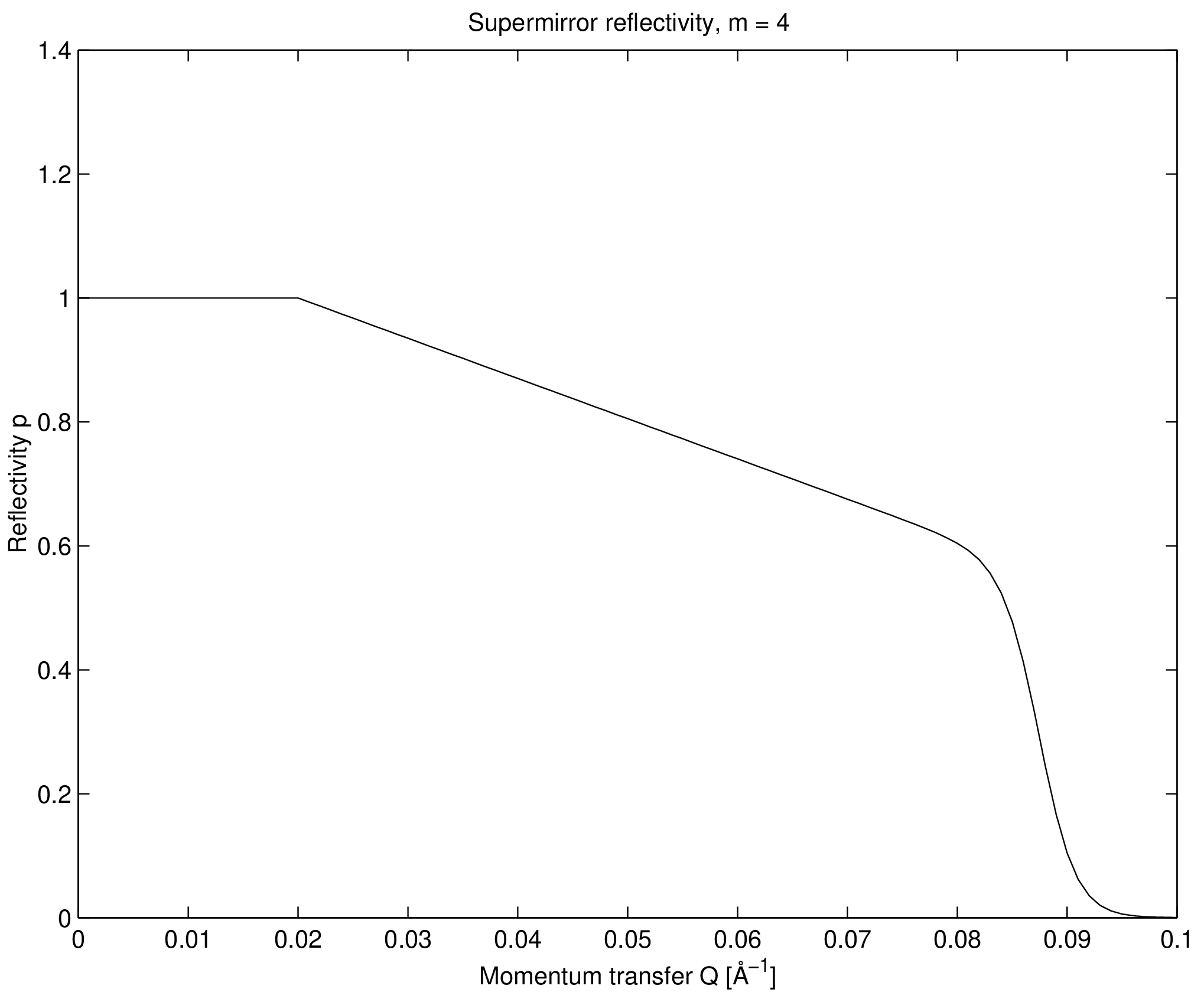
| Figure 5.1.: | A typical reflectivity curve for a supermirror, Eq. (5.2). The used values are \( m=4\), \(R_0=1\), \(Q_\textrm {c} = 0.02\) Å\(^{-1}\), \(\alpha = 6.49\) Å, \( W=1/300\) Å\(^{-1}\). |
Guide: The guide section
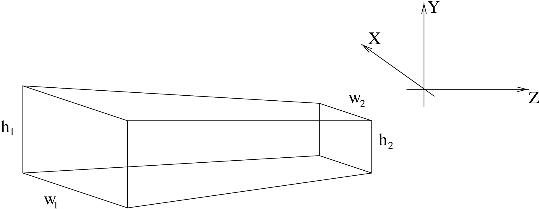
The component Guide models a guide tube consisting of four flat mirrors. The guide is centered on the \(z\) axis with rectangular entrance and exit openings parallel to the \(x\)-\(y\) plane. The entrance has the dimensions \((w_1,h_1)\) and placed at \(z=0\). The exit is of dimensions \((w_2,h_2)\) and is placed at \(z=l\) where \(l\) is the guide length. See figure 5.2. The reflecting properties are given by the values of \(R_0, m, Q_c, W\), and \(\alpha \), as for Mirror, or alternatively from the reflectivity file \(reflect\).
Guide may produce wrong results with gravitation support. Use Guide_gravity (section 5.1.0.0) in this case, or the Guide_channeled in section 5.1.0.0.
Guide geometry and reflection
For computations on the guide geometry, we define the planes of the four guide sides by giving their normal vectors (pointing into the guide) and a point lying in the plane: \[ \begin {array}{rclcrcl} \textbf {n}^v_1 &=& (l, 0, {(w_2 - w_1) / 2}) & & \textbf {O}^v_1 &=& (- w_1 / 2, 0, 0) \\ \textbf {n}^v_2 &=& (-l, 0, {(w_2 - w_1) / 2}) & & \textbf {O}^v_2 &=& (w_1 / 2, 0, 0) \\ \textbf {n}^h_1 &=& (0, l, {(h_2 - h_1) / 2}) & & \textbf {O}^h_1 &=& (0, - h_1 / 2, 0) \\ \textbf {n}^h_2 &=& (0, -l, {(h_2 - h_1) / 2}) & & \textbf {O}^h_2 &=& (0, h_1 / 2, 0) \\ \end {array} \] In the following, we refer to an arbitrary guide side by its origin O and normal n.
With these definitions, the time of intersection of the neutron with a guide side can be computed by considering the projection onto the normal: \begin {equation} t^\alpha _\beta = \frac {(\textbf {O}^\alpha _\beta - \textbf {r}_0) \cdot \textbf {n}^\alpha _\beta } {\textbf {v} \cdot \textbf {n}^\alpha _\beta } , \end {equation} where \(\alpha \) and \(\beta \) are indices for the different guide walls, assuming the values (h,v) and (1,2), respectively. For a neutron that leaves the guide directly through the guide exit we have \begin {equation} t_\textrm {exit} = \frac {l - z_0}{v_z} \end {equation}
The reflected velocity \(\textbf {v}_\textrm {f}\) of the neutron with incoming velocity \(\textbf {v}_\textrm {i}\) is computed by the formula \begin {equation} \textbf {v}_\textrm {f} = \textbf {v}_\textrm {i} - 2{\textbf {n} \cdot \frac {\textbf {v}_\textrm {i}}{{|\textbf {n}|^2}} \textbf {n}} \end {equation} This expression is arrived at by again considering the projection onto the mirror normal (see figure 5.3). The reflectivity of the mirror is taken into account as explained in section 5.1.
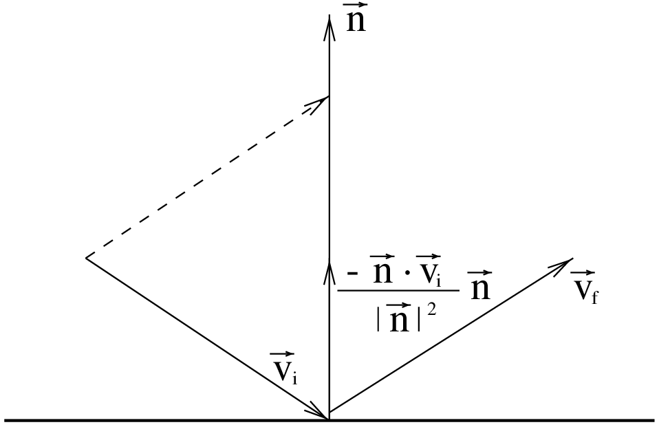
| Figure 5.3.: | Neutron reflecting from mirror. \(\textbf {v}_\textrm {i}\) and \(\textbf {v}_\textrm {f}\) are the initial and final velocities, respectively, and n is a vector normal to the mirror surface. |
Algorithm
-
The neutron is initially propagated to the \(z = 0\) plane of the guide entrance.
-
If it misses the entrance, it is ABSORB’ed.
-
Otherwise, repeatedly compute the time of intersection with the four mirror sides and the guide exit.
-
The smallest positive \(t\) thus found gives the time of the next intersection with the guide (or in the case of the guide exit, the time when the neutron leaves the guide).
-
Propagated the neutron ray to this point.
-
Compute the reflection from the side.
-
Update the neutron weight factor by the amount \(\pi _i = R(Q)\).
-
Repeat this process until the neutron leaves the guide.
There are a few optimizations possible here to avoid redundant computations. Since the neutron is always inside the guide during the computations, we always have \((\textbf {O} - \textbf {r}_0) \cdot \textbf {n} \leq 0\). Thus \(t \leq 0\) if \(\textbf {v} \cdot \textbf {n} \geq 0\), so in this case there is no need to actually compute \(t\). Some redundant computations are also avoided by utilizing symmetry and the fact that many components of n and O are zero.
Guide_channeled: A guide section component with multiple channels
| Name: | Guide_channeled |
| Author: | System |
| Input parameters | \(w_1, h_1\), \(w_2, h_2\), \(l\), \(k\), \(m_x, m_y\) |
| Optional parameters | \(d, R_0, Q_{cx}, Q_{cy}, W, \alpha _x, \alpha _y\) |
| Notes | validated, no gravitation support |
The component Guide_channeled is a more complex variation of Guide described in the previous section. It allows the specification of different supermirror parameters for the horizontal and vertical mirrors, and also implements guides with multiple channels as used in neutron bender devices. By setting the \(m\) value of the supermirror coatings to zero, nonreflecting walls are simulated; this may be used for a very detailed simulation of a Soller collimator, see section 4.5.
The input parameters are \(w_1\), \(h_1\), \(w_2\), \(h_2\), and \(l\) to set the guide dimensions as for Guide (entry window, exit window, and length); \(k\) to set the number of channels; \(d\) to set the thickness of the channel walls; and \(R_0\), \(W\), \(Q_{cx}\), \(Q_{cy}\), \(\alpha _x\), \(\alpha _y\), \(m_x\), and \(m_y\) to set the supermirror parameters as described under Guide (the names with x denote the vertical mirrors, and those with y denote the horizontal ones).
Algorithm
The implementation is based on that of Guide.
-
Calculate the channel which the neutron will enter.
-
Shift the \(x\) coordinate so that the channel can be simulated as a single instance of the Guide component.
-
(do the same as in Guide.)
-
Restore the coordinates when the neutron exits the guide or is absorbed.
Known problems
-
This component may produce wrong results with gravitation support. Use Guide_gravity (section 5.1.0.0) in this case.
-
The focusing channeled geometry (for \(k > 1\) and different values of \(w_1\) and \(w_2\)) is buggy (wall slopes are not computed correctly, and the component ’leaks’ neutrons).
Guide_gravity: A guide with multiple channels and gravitation handling
| Name: | Guide_gravity |
| Author: | System |
| Input parameters | \(w_1, h_1\), \(w_2, h_2\), \(l\), \(k\), \(m\) |
| Optional parameters | \(d, R_0, Q_c, W, \alpha \), wavy, chamfers, \(k_h\), \(n\), \(G\) |
| Notes | validated, with gravitation support, rotating mode |
This component is a variation of Guide_channeled (section 5.1.0.0) with the ability to handle gravitation effects and functional channeled focusing geometry. Channels can be specified in two dimensions, producing a 2D array (\(k, k_h\)) of smaller rectangular guide channels.
The coating is specified as for the Guide and Mirror components by mean of the parameters \(R_0, m, Q_c, W\), and \(\alpha \), or alternatively from the reflectivity file \(reflect\).
Waviness effects, supposed to be randomly distributed (i.e. non-periodic waviness) can be specified globally, or for each part of the guide section. Additionally, chamfers may be defined the same way. Chamfers originate from the substrate manufacturing, so that operators do not harm themselves with cutting edges. Usual dimensions are about tens of millimeters. They are treated as absorbing edges around guide plates, both on the input and output surfaces, but also aside each mirror.
The straight section of length \(l\) may be divided into \(n\) bits of same length within which chamfers are taken into account.
The component has also the capability to rotate at a given frequenccy in order to approximate a Fermi Chopper, including phase shift. The approximation resides in the fact that the component is considered fixed during neutron propagation inside slits. Beware that this component is then located at its entry window (not centered as the other Fermi choppers).
To activate gravitation support, either select the McStas gravitation support (mcrun --gravitation ... or from the Run dialog of mcgui), or set the gravitation field strength \(G\) (e.g. -9.81 on Earth).
This component is about 50 % slower than the Guide component, but has much more capabilities.
A contributed version Guide_honeycomb of this component exists with a honeycomb geometry.
Bender: a bender model (non polarizing)
| Name: | Bender |
| Author: | Philipp Bernhardt |
| Input parameters | \(r, W_{in},l,w,h \) |
| Optional parameters | \(k,d,R_{0[a,i,s]},\alpha _{[a,i,s]},m_{[a,i,s]},Q_{c[a,i,s]},W_{[a,i,s]}\) |
| Notes | partly validated, no gravitation support |
The Bender component is simulating an ideal curved neutron guide (bender). It is bent to the negative X-axis and behaves like a parallel guide in the Y axis. Opposite curvature may be achieved by a \((0,0,180)\) rotation (along Z-axis).
Bender radius \(r\), entrance width \(w\) and height \(h\) are required parameters. To define the length, you may either enter the deviation angle \(W_{in}\) or the length \(l\). Three different reflectivity profiles \(R_0,Q_c,W,m,\alpha \) can be given (see section 5.1): for outer walls (index \(a\)), for inner walls (index \(i\)) and for the top and bottom walls (index \(s\)).
To get a better transmission coefficient, it is possible to split the bender into \(k\) channels which are separated by partitions with the thickness of \(d\). The partitioning walls have the same coating as the exterior walls.
Because the angle of reflection doesn’t change, the routine calculates the reflection coefficent for the concave and, if necessary, for the convex wall only onces, together with the number of reflections. Nevertheless the exact position, the time, and the divergence is calculated at the end of the bender, so there aren’t any approximations.
The component is shown straight on geometrical views (mcdisplay/Trace), and the next component may be placed directly at distance \(r.W_{in} = l\) without rotation.
Results have been compared succesfully with analytical formula in the case of an ideal reflection and cross-checked with the program haupt.
An other implementation of the Bender is available as the contributed component Guide_curved.
Curved guides
Real curved guides are usually made of many straight elements (about 1 m long) separated with small gaps (e.g. 1 mm). Sections of about 10 m long are separated with bigger gaps for accessibility and pumping purposes.
We give here an example description of such a section. Let us have a curved guide of total length \(L\), made of \(n\) elements with a curvature radius \(R\). Gaps of size \(d\) separate elements from each other. The rotation angle of individual straight guide elements is \(\alpha _z = (L+d)/R*180/\pi \) in degrees.
In order to build an independent curved guide section, we define Arm components at the begining and end of it.
1COMPONENT CG_In = Arm() AT (...)
2
3COMPONENT CG_1  = Guide_gravity(l=L/n, ...)
4AT (0,0,0) RELATIVE PREVIOUS
5
6COMPONENT CG_2  = Guide_gravity(l=L/n, ...)
7AT (0,0,L/n+d) RELATIVE PREVIOUS
8ROTATED (0, (L/n+d)/R*180/PI, 0) RELATIVE PREVIOUS
9...
10COMPONENT CG_Out = Arm() AT (0,0,L/n) RELATIVE PREVIOUS
The Guide component should be duplicated \(n\) times by copy-paste, but changing the instance name, e.g. CG_1, CG_2, ..., CG_n. This may be automated with the COPY or the JUMP ITERATE mechanisms (see User manual).
An implementation of a continuous curved guide has been contributed as component Guide_curved.