6.1 The DiskChopper McStas Component
Based on Chopper (Philipp Bernhardt), Jitter and beamstop from work by Kaspar Hewitt Klenoe (jan 2006), adjustments by Rob Bewey (march 2006)
Identification
-
Author: Peter Willendrup
-
Origin: Risoe
-
Date: March 9 2006
Description
Models a disc chopper with nslit identical slits, which are symmetrically distributed on the disc. At time t=0, the centre of the first slit opening will be situated at the vertical axis when phase=0, assuming the chopper centre of rotation is placed BELOW the beam axis. If you want to place the chopper ABOVE the beam axis, please use a 180 degree rotation around Z (otherwise unexpected beam splitting can occur in combination with the isfirst=1 setting, see related bug on GitHub)
For more complicated gemometries, see component manual example of DiskChopper GROUPing.
If the chopper is the 1st chopper of a continuous source instrument, you should use the "isfirst" parameter. This parameter SETS the neutron time to match the passage of the chooper slit(s), taking into account the chopper timing and phasing (thus conserving your simulated statistics).
The isfirst parameter is ONLY relevant for use in continuous source settings.
Example: DiskChopper(radius=0.2, theta_0=10, nu=41.7, nslit=3, delay=0, isfirst=1) First chopper DiskChopper(radius=0.2, theta_0=10, nu=41.7, nslit=3, delay=0, isfirst=0)
NOTA BENE wrt. GROUPing and isfirst: When setting up a GROUP of DiskChoppers for a steady-state / reactor source, you will need to set up 1) An initial chopper with isfirst=1, NOT part of the GROUP - and using a "big" chopper opening that spans the full angular extent of the openings of the subsequent GROUP 2) Add your DiskChopper GROUP setting isfirst=0
Input parameters
Parameters in boldface are required; the others are optional.
|
Name |
Unit |
Description |
Default |
|
|
|||
|
theta_0 |
deg |
Angular width of the slits. |
0 |
|
radius |
m |
Radius of the disc |
0.5 |
|
yheight |
m |
Slit height (if = 0, equal to radius). Auto centering of beam at half height. |
|
|
nu |
Hz |
Frequency of the Chopper, omega=2*PI*nu (algebraic sign defines the direction of rotation) |
|
|
nslit |
1 |
Number of slits, regularly arranged around the disk |
3 |
|
jitter |
s |
Jitter in the time phase |
0 |
|
delay |
s |
Time ’delay’ |
0 |
|
isfirst |
0/1 |
Set it to 1 for the first chopper position in a cw source (it then spreads the neutron time distribution) |
0 |
|
n_pulse |
1 |
Number of pulses (Only if isfirst) |
1 |
|
abs_out |
0/1 |
Absorb neutrons hitting outside of chopper radius? |
1 |
|
phase |
deg |
Angular ’delay’ (overrides delay) |
0 |
|
xwidth |
m |
Horizontal slit width opening at beam center |
0 |
|
verbose |
1 |
Set to 1 to display Disk chopper configuration |
0 |
|
|
|||
|
|
|||
|
|
|||
Links
-
Component source code found in file DiskChopper.comp.
The disc chopper
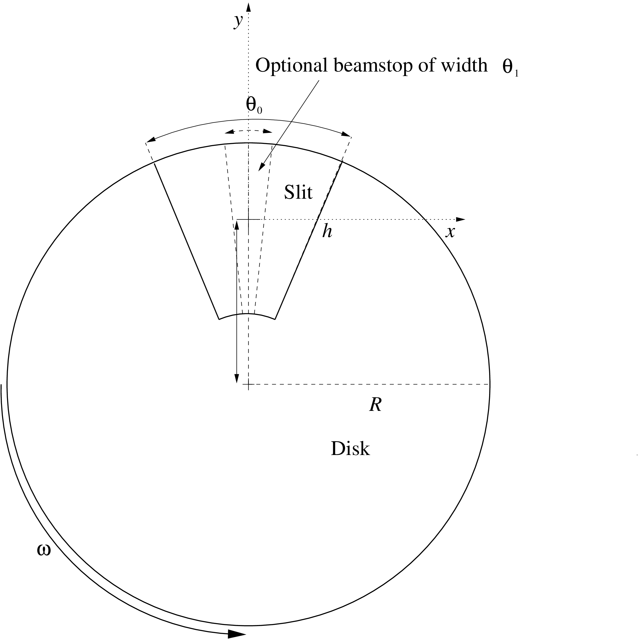
To cut a continuous neutron beam into short pulses, or to control the pulse shape (in time) from a pulsed source, one can use a disc chopper (see figure 6.1). This is a fast rotating disc with the rotating axis parallel to the neutron beam. The disk consists of neutron absorbing materials. To form the pulses the disk has openings through which the neutrons can pass.
Component DiskChopper is an infinately thin, absorbing disc of radius \(R\) with \(n\) slit openings of height \(h\) and angular width \(\theta _0\). The slits are symmetrically disposed on the disc. If unset, the slit height \(h\) will extend to the centre of the disc (\(h=R\)).
The DiskChopper is self-centering, meaning that the centre of the slit openings will automatically be positioned at the centre of the beam axis (see figure 6.1). To override this behaviour, set the paramter \(compat=1\), positioning the chopper centre at height \(-R\) - as implemented in the original Chopper component.
Optionally, each slit can have a central, absorbing insert - a beamstop of angular width \(\theta _1\). For more exotic chopper definitions, use the GROUP keyword, see below for an example.
The direction of rotation can be controlled, which allows to simulate e.g. counter-rotating choppers. The phase or time-delay \(t_0\) (in seconds) is defined by the time where the first of the \(n\) slits is positioned at the top. As an alternative, an angular phase can be given using the \(\phi _0\) parameter.
By default, neutrons hitting outside the physical extent of the disc are absorbed. This behaviour can be overruled by setting parameter \(abs\_out=0\).
When simulating the chopping of a continuous beam, most of the neutrons could easily be lost. To improve efficiency, one can set the flag IsFirst, which will allow every neutron ray to pass the DiskChopper, but modify the time, \(t\), to a (random) time at which it is possible to pass. Of course, there should be only one “first chopper” in any simulation. To simulate frame overlap from a “first chopper”, one can specify the number of frames to study by the parameter \(n_\textrm {pulse}\).
For more advanced chopper geometries than those mentioned above, it is possible to set up a GROUP of choppers:
1COMPONENT Chop1 = DiskChopper(omega=2500, R=0.3, h=0.2, theta_0=20, n=1)
2AT (0, 0, 1.1) RELATIVE Source
3GROUP Choppers
4
5COMPONENT Chop2 = DiskChopper(omega=2500, R=0.3, h=0.2, theta_0=20, n=1,
6                             phi_0=40)
7AT (0, 0, 1.1) RELATIVE Source
8GROUP Choppers
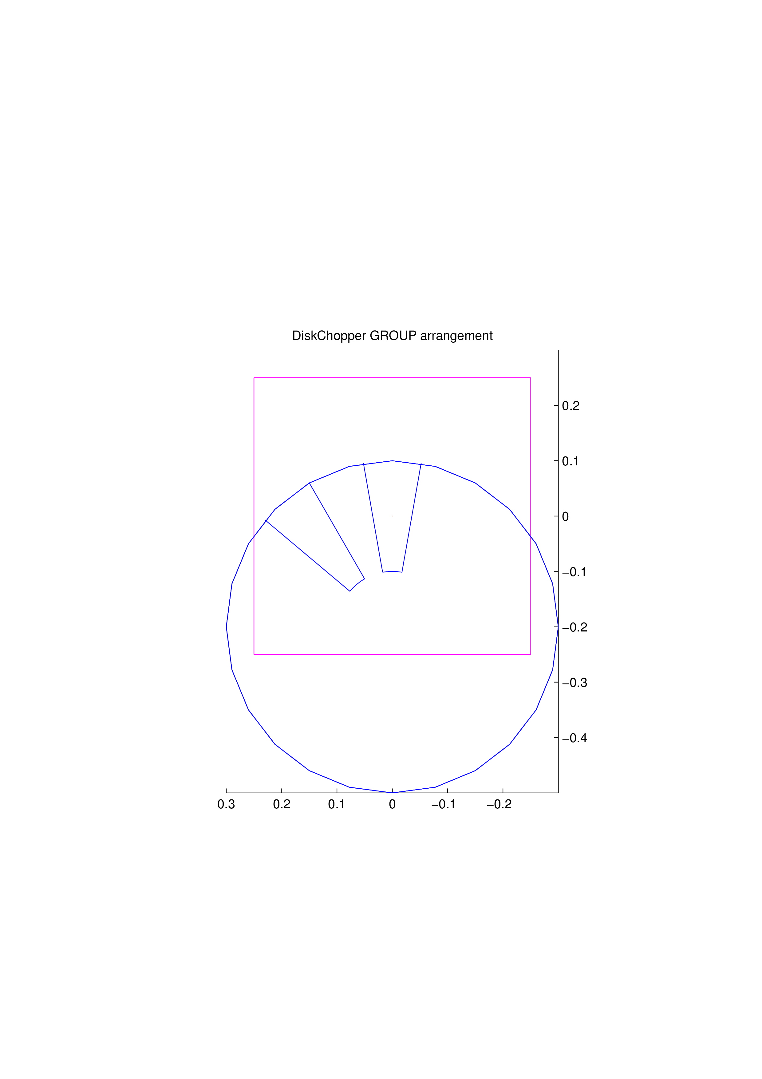
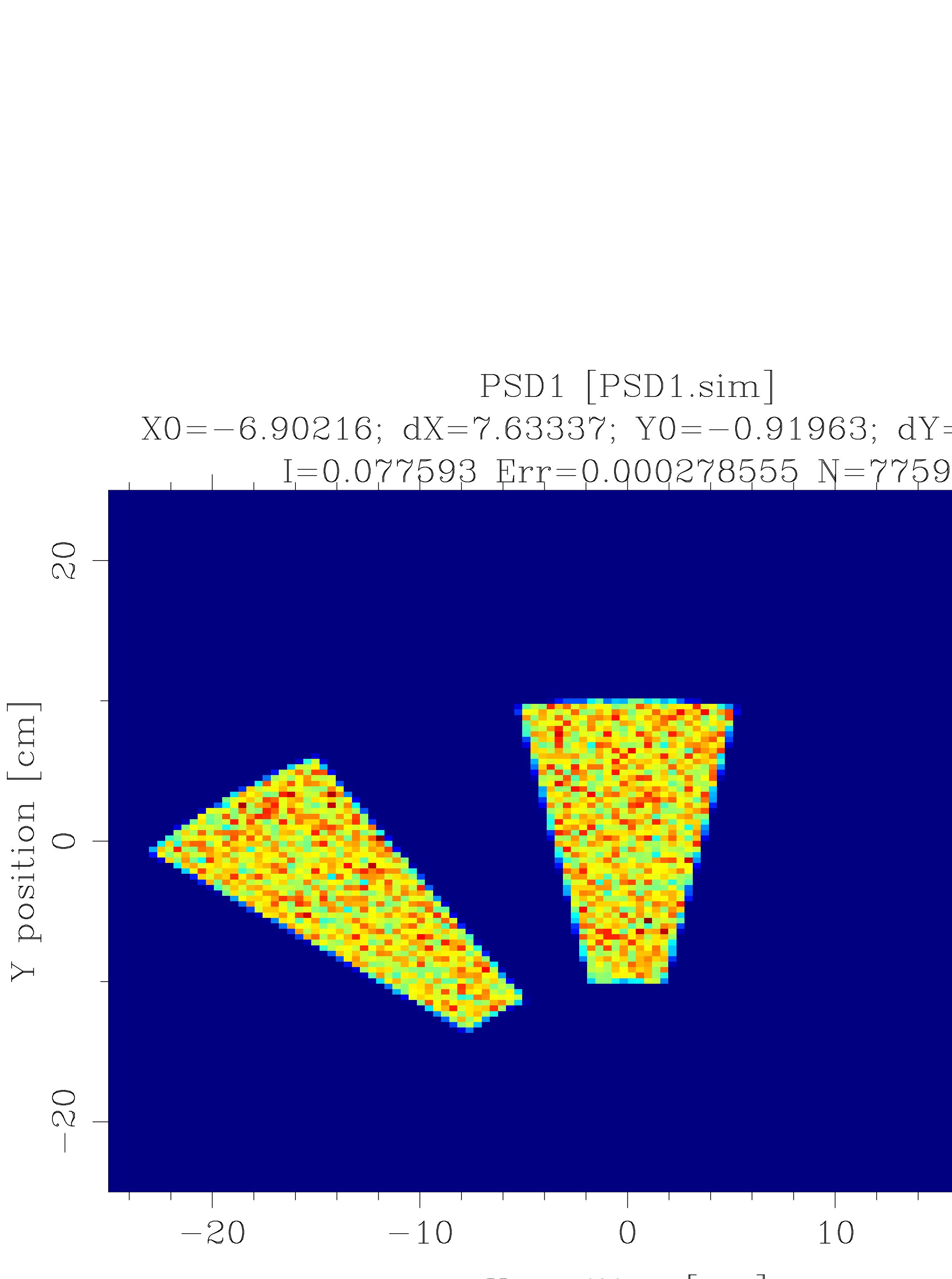
The result of such a DiskChopper GROUPing can be seen in figure 6.2