6.3 The Vitess_ChopperFermi McStas Component
Fermi chopper with absorbing walls using the VITESS module ’chopper_fermi’
Identification
-
Author: Geza Zsigmond
-
Origin: VITESS module ’chopper_fermi’
-
Date: Sep 2004
Description
This component simulates a Fermi chopper with absorbing walls. The rotation axis is vertical (y-axis), i.e. the path length through the channels is given by the length ’depth’ along the z-axis. The shape of the channels can be straight, curved with circular, or curved with ideal (i.e. close to a parabolic) shape. This is determined by the parameter ’GeomOption’.
Geometry for straight and circular channels: The geometry of the chopper consists of a rectangular shaped object with a channel system. In transmission position, there are ’Nchannels’ slits along the x-axis, separated by absorbing walls of thickness ’wallwidth’ giving a total width ’width’. The rectangular channel system is surrounded by a so-called shadowing cylinder (cf component manual).
Geometry for parabolic channels: In this case, the Fermi chopper is supposed to be a full cylinder, i.e. the central channels are longer than those on the edges (cf. figure in the component manual). The other features are the same as for the other options.
Apart from the frequency of rotation, the phase of the chopper at t=0 has to be given; phase = 0 means transmission orientation.
The option ’zerotime’ may be used to reset the time at the chopper position. The consequence is that only 1 pulse is generated instead of several.
NOTE: This component must NOT be located at the same position as the previous one. This also stands for monitors and Arms. A non zero distance must be defined.
Examples: straight Fermi chopper, 18000 rpm, 20 channels a 0.9 mm separated by 0.1 mm walls, 16 mm channel length, minimal shadowing cylinder, phased to be open at 1 ms, generation of only 1 pulse, normal precision (for short wavelength neutrons) Vitess_ChopperFermi(GeomOption=0, zerotime=1, Nchannels=20, Ngates=4,
freq=300.0,   height=0.06, width=0.0201,
depth=0.016,  r_curv=0.0,  diameter=0.025691, Phase=-108.0,
wallwidth=0.0001, sGeomFileName="FC_geom_str.dat")
Fermi chopper with circular channels, 12000 rpm, optimized for 6 Å, several pulses, highest accuracy (because of long wavelength neutrons used), rest as above
Vitess_ChopperFermi(GeomOption=2, zerotime=0,    Nchannels=20,  Ngates=8,
freq=200.0,   height=0.06,   width=0.0201,
depth=0.016,  r_curv=0.2623, diameter=0.025691, Phase=-72.0,
wallwidth=0.0001, sGeomFileName="FC_geom_circ.dat")
%VALIDATION Apr 2005: extensive external test, most problems solved (cf. ’Bugs’ and source header) Validated by: K. Lieutenant
limitations: slow (10 times slower than FermiChopper), especially for a high number of channels
%BUGS reduction of transmission by a large shadowing cylinder underestimated
Input parameters
Parameters in boldface are required; the others are optional.
|
Name |
Unit |
Description |
Default |
|
|
|||
|
sGeomFileName |
str |
name of output file for geometry information |
0 |
|
GeomOption |
1 |
option: 0:straight 1:parabolic 2:circular |
0 |
|
zerotime |
1 |
option: 1:’set time to zero’ 0: ’do not’ |
0 |
|
Nchannels |
1 |
number of channels of the Fermi chopper |
20 |
|
Ngates |
1 |
number of gates defining the channel: 4=default, 6 or 8 for long wavelengths |
4 |
|
freq |
Hz |
number of rotations per second |
300.0 |
|
height |
m |
height of the Fermi chopper |
0.05 |
|
width |
m |
total width of the Fermi chopper |
0.04 |
|
depth |
m |
channel length of the Fermi chopper |
0.03 |
|
r_curv |
m |
radius of curvature of the curved Fermi chopper |
0.5 |
|
diameter |
m |
diameter of the shadowing cylinder |
0.071 |
|
Phase |
deg |
dephasing angle at zero time |
0.0 |
|
wallwidth |
m |
thickness of walls separating the channels |
0.0002 |
|
|
|||
|
|
|||
|
|
|||
Links
-
Component source code found in file Vitess_ChopperFermi.comp.
The Fermi Chopper from Vitess
The component Vitess_ChopperFermi simulates a Fermi chopper with absorbing walls. The shape of the channels can be straight, curved with circular, or curved with ideal (i.e. close to a parabolic) shape. This is determined by the parameter ’GeomOption’. In the option ’straight Fermi chopper’, the very fast neutrons are transmitted with only a time modulation and lower speed neutrons are modulated both in time of flight and wavelength. If the channels are curved, the highest transmission occurs for a wavelength
\begin {equation} \lambda _\textrm {opt} = \frac {3956 \textrm {[m\AA /s]}}{2 \omega r_\textrm {curv}} \end {equation}
with
\begin {equation} \omega = 2 \pi f \end {equation}
The optimal shape is calculated in an exact way and is close to parabolic; in this case, transmission is as high for the optimal wavelength as in the case of a straight Fermi chopper for the limit \(\lambda \rightarrow 0\). In the more realistic case of circular shapes channels, the transmission is slightly lower. In general, neutrons are transmitted through a curved Fermi chopper with a time AND wavelength modulation .
The rotation axis is vertical (y-axis), i.e. the path length through the channels is given by the length \(l\) along the z-axis. The inital orientation is given by the phase \(\phi \) of the chopper - \(\phi \) = 0 means transmission orientation.
Geometry for straight and circular channels: The geometry of the chopper consists of a rectangular shaped object with a channel system. In transmission position, there are \(N_\textrm {gates}\) slits of width \(w_\textrm {slit}\) each along the x-axis, separated by absorbing walls of thickness \(w_\textrm {wall}\) (see figure 6.6). The total width \(w_\textrm {tot}\) is given by
\begin {equation} w_\textrm {tot} = N_\textrm {gates} w_\textrm {slit} + (N_\textrm {gates}+1) w_\textrm {wall} \end {equation}
The rectangular channel system is surrounded by a so-called shadowing cylinder; it is a part of a cylinder with vertical symmetry axis and diameter
\begin {equation} d \geq \sqrt {l^2 + w_\textrm {tot}^2} \end {equation}
It serves to prevent transmission of neutrons which do not fly through the channels; but it also reduces the transmission, because the cylinder removes neutrons in front of the channel entrance or behind the channel exit (see figure 6.6).
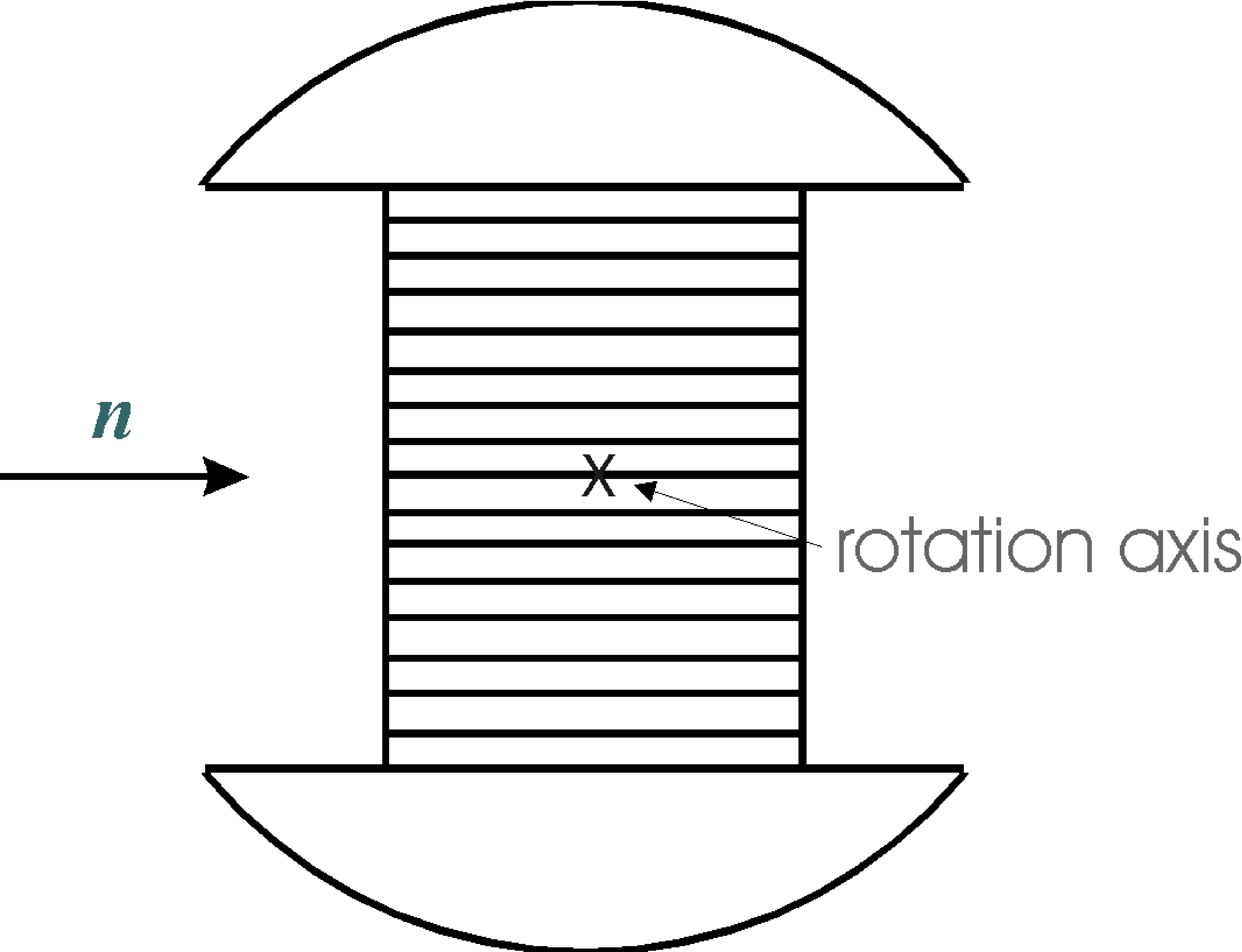
Geometry for parabolic channels: In this case, the Fermi chopper is supposed to be a full cylinder, i.e. the central channels are longer than those on the edges. The other features are the same as for the other options. (see figure 6.7).
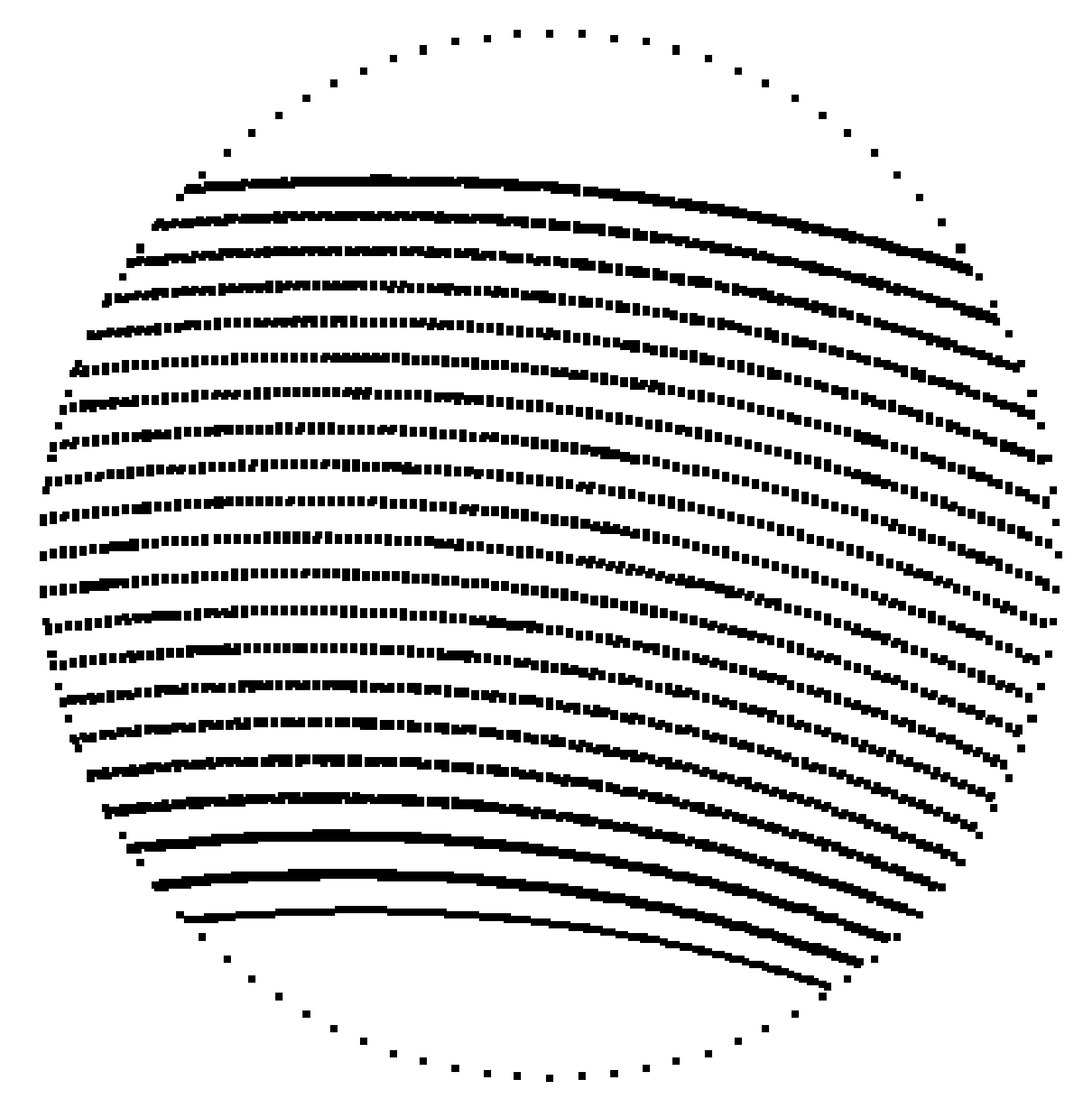
The algorithm works with a rotating chopper framework. Neutrons hitting the channel walls are absorbed. The channels are approximated by \(N_\textrm {gates}\) gates. If the trajectory takes a course through all the gates, the neutron passes the Fermi chopper. There are gates at the entrance and the exit of the channel. The other gates are situated close to the centre of the Fermic chopper. Precision of the simulation increases with the number of gates, but also the computing time needed. The use of four channels already gives exact transmission shapes for lower wavelengths (\(\lambda < 6\) Å) and good approximation for higher ones. It is recommended to use larger number of channels only for a check.
The option ’zerotime’ may be used to reset the time at the chopper position. The time is set to a value between -\(T_\textrm {p}\)/2 and +\(T_\textrm {p}\)/2 (with \(T_\textrm {p}\) being the maximal pulse length), depending on the phase of the chopper at the moment of passing the chopper centre. The result is the generation of only 1 pulse instead of several; this is useful for TOF instruments on continuous sources.
This component is about twice slower than the FermiChopper component.
The component must be placed after a component which sets a non zero flight path to the Fermi Chopper (e.g. not an Arm).